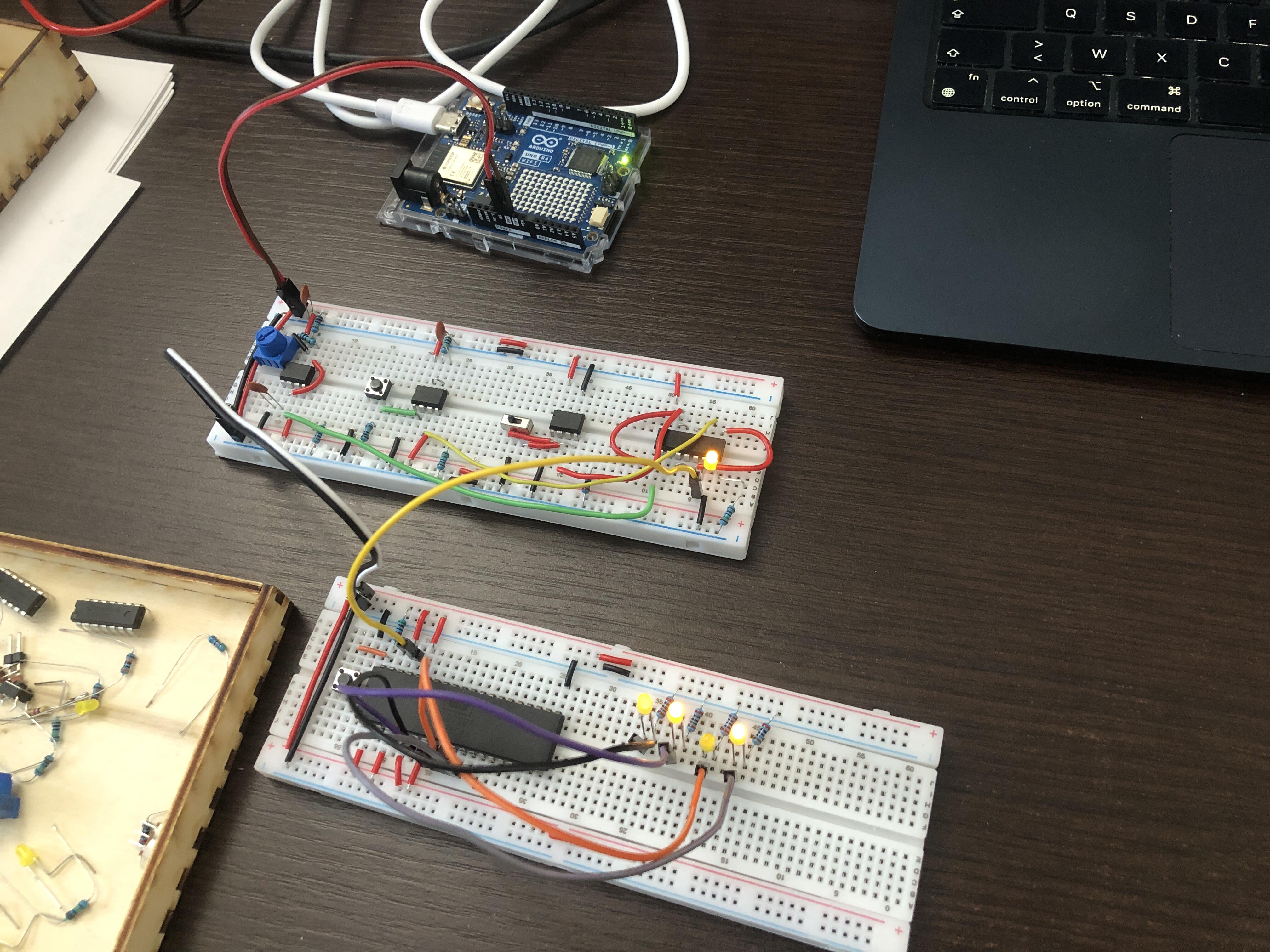
Hardware emulation
I play video games on emulators and I understand the basic principles of emulation, but I want to learn more and get first hand experience. Sure it would be cool to learn how to write a Game Boy emulator, and it’s probably doable with enough patience, but I like to start from the basics. That is why I set out to build a custom hardware system and write an emulator for it. This will allow me to start slow and discover the fundamental principles of emulation, adding complexity at my onw pace.
I chose to use the 6502 processor and its 6522 interface, taking reference from Ben Eater’s excellent video series dedicated to those components. The 6502 was the CPU of many consumer devices in the 1980s, notably the Apple II, Commodore 64 and Atari 2600. It is a relatively simple microprocessor, ideal for beginners. Modernized versions are still in production today, and there’s a large community of enthusiasts.
The user interface of my system will initially be minimal, consisting only of buttons and LEDs, and perhaps a small OLED display. This project is primarily an exploration. It is an opportunity to learn low-level hardware concepts and gain experience with the interaction between hardware and software.
In this kind of exploratory project, I like to start from the basics and experiment incrementally with the components, validating expected behavior step by step, comparing my predictions with reality, and building a solid understanding of how things work. I therefore began by familiarizing myself with the 6502, experimenting with the address and data buses, the reset vector, and so on. I then moved on to an EEPROM, which I initially programmed manually on a breadboard by directly manipulating the control signals, before eventually designing an Arduino-driven automatic programming circuit.
I am now running into difficulties with the 6522 interface chip, which led me to build D flip-flops from scratch and interface them directly with the 6502—a completely unexpected but fascinating detour. My next goal is to apply a similar approach to connect at least one button, allowing me to start writing interactive programs and begin thinking seriously about emulation itself.
I have documented this project as it progressed through a series of posts detailing each work session. This page provides a summary of the project in its current state and offers some broader reflections on the discoveries I’ve made. It is continuously updated as the project advances and as my understanding evolves. Links to the detailed posts can be found throughout the relevant sections. A complete list of publications is available here.
My thoughts on emulation
Writing an emulator first demands to understand how each instruction of a program written for the original electronic system affects the components that interact with the user. This requires a good understanding of the original hardware and the interaction between hardware and software, but it does not necessarily mean faithfully reproducing the internal behavior of every electronic component. What really matters are the elements the user interacts with.
Take the Game Boy as an example. Its user-facing interfaces are the directional pad, the A and B buttons, and the Start and Select buttons for input, along with the screen and speaker for output. The goal of an emulator is therefore to take a game’s code—originally written to drive the Game Boy’s hardware—and use the PC’s hardware to recreate the visuals and sounds that the Game Boy would have produced.
A program may use the hardware in unusual ways, or a user may discover a bug or design flaw that allows the system to be used in an unintended or undocumented manner. Emulator developers must decide which of these behaviors are worth supporting, keeping in mind that any simulation is necessarily imperfect.
This last point is precisely what I want to explore in this project. At what level of accuracy does hardware need to be simulated? Is it always possible to infer the intention behind a sequence of instructions? Consider a device connected to the CPU via I²C, where programs normally use the provided driver. What happens if a program decides to implement the I²C protocol entirely in software instead? What would supporting that use case imply for the emulator’s design?
Hardware used in this project
For the most part, I use the same components as Ben Eater in his videos, or the closest equivalents I can find on AliExpress. Some components came from my own stock. I use my Arduino to program the ROM, observe signals, experiment with components, and also as a power supply.
| Item | Ref | Link |
|---|---|---|
| CPU | 6502 | AliExpress |
| EEPROM | AT28C256 | AliExpress |
| RAM | 62256 | AliExpress |
| Logic gates |
74LS00
74LS02 74LS04 74LS08 |
AliExpress |
| Shift registers | 74HC595 | AliExpress |
| Interface | 6522 | AliExpress |
| LEDs | (stock) | |
| Buttons | AliExpress | |
| OLED screen | SSD1306 | AliExpress |
| Breadboards | AliExpress | |
| Jumper wire | AliExpress | |
| Dupont wires | AliExpress | |
| Resistors | AliExpress | |
| Transistors | P2N2222A | AliExpress |
| Arduino | Uno R4 Wi-Fi | Arduino Shop |
First steps with the 6502
I started by installing the 6502 on a breadboard, wiring the value 0xEA onto the data bus, which corresponds to the NOP (“No Operation”) instruction, and connecting LEDs to the four least significant bits of the address bus. To generate the clock signal, I use a 555-timer-based module that I built by following Ben Eater’s videos on the subject. The LEDs display a counting pattern, indicating that the processor is advancing through the program.
First steps with the 6502
Read
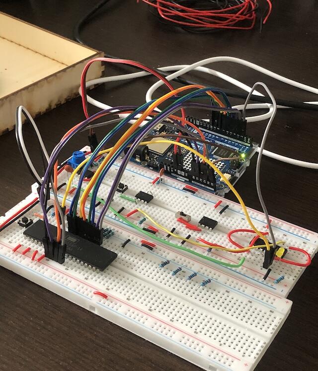
I then connected the address and data buses, as well as the read/write signal, to an Arduino and wrote code capable of supplying data on the bus according to the address requested by the CPU. I used this rudimentary setup to provide the CPU with a minimal three-instruction program and verified correct operation by observing bus activity.
For this kind of experiment, the Arduino generates the clock signal. I chose this approach to ensure that I was reading from and writing to the buses at the correct times, since I have not yet studied the 6502’s timing characteristics in detail.
Running our first program and introducing the EEPROM
Read
Introducing the EEPROM
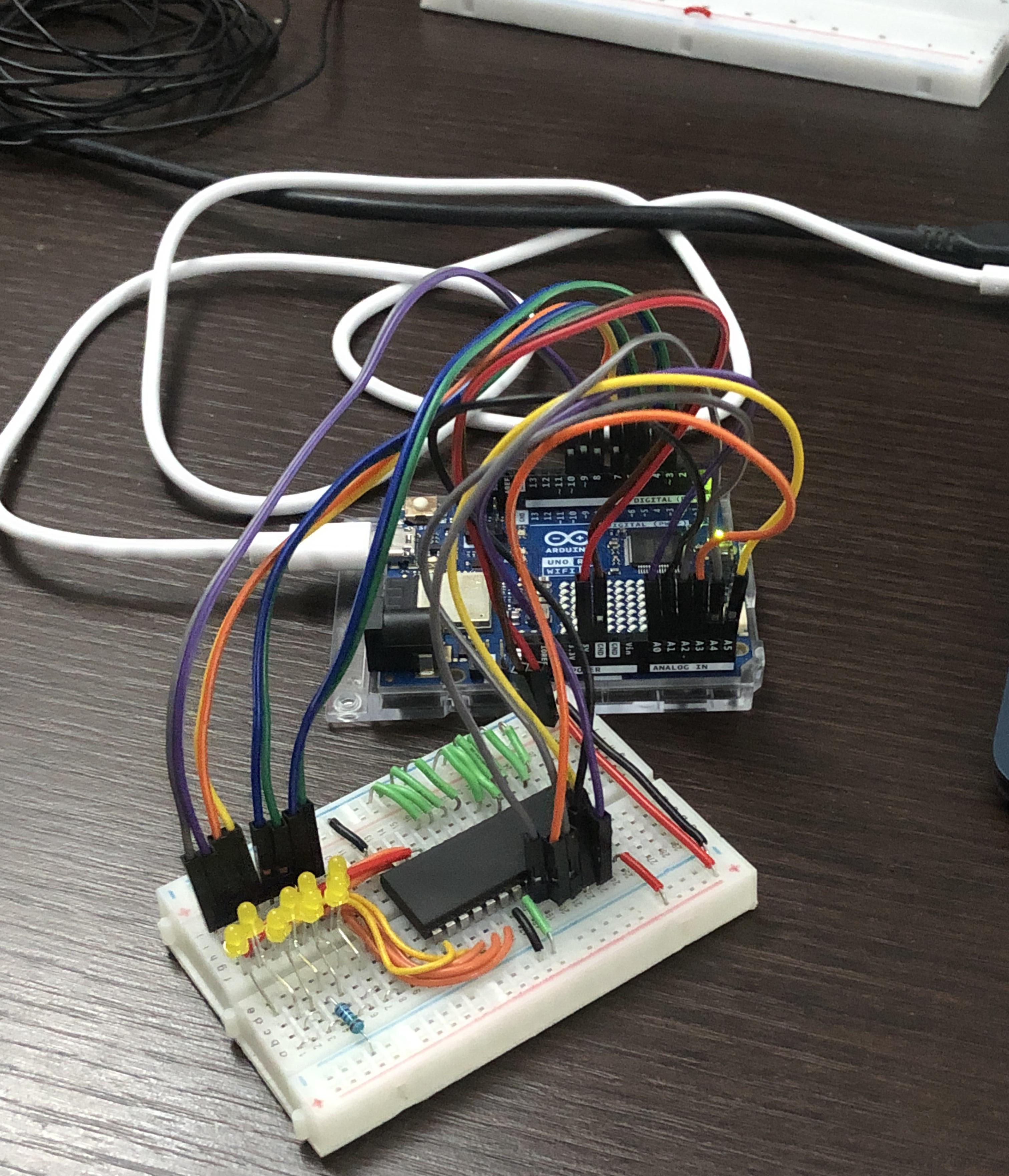
The Arduino setup was useful for testing, but in the final system the EEPROM will provide the data. Staying true to the spirit of the project, I started from the basics by performing reads and writes through direct manipulation of the control signals, using LEDs to visualize the data. I then wrote Arduino code capable of reading and writing, first one byte at a time and eventually entire sequences.
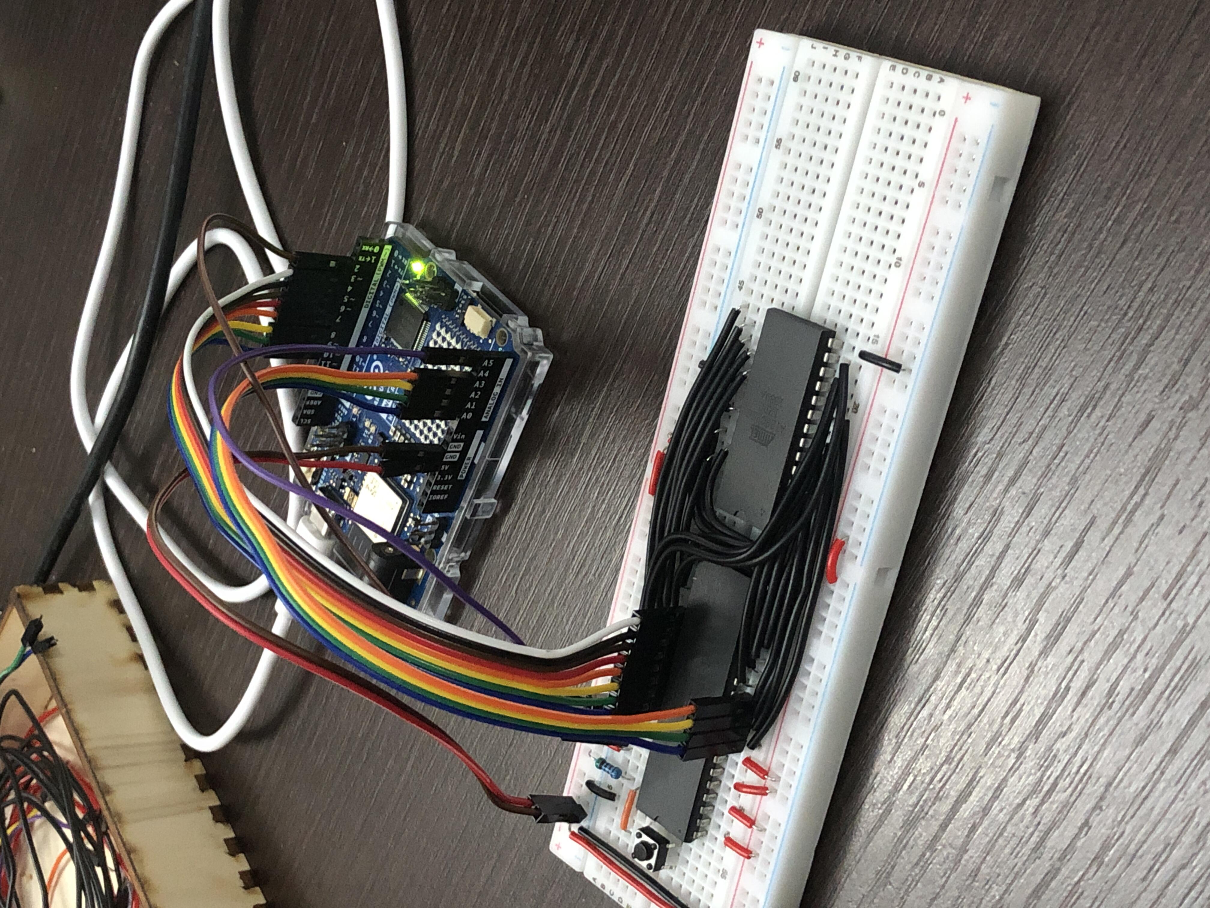
Once I was able to program the ROM, I connected it to the 6502, initially as a temporary setup and later as a semi-permanent assembly while trying to keep the wiring reasonably tidy.
EEPROM setup and connection to the 6502
Read
Building a programmer with shift registers
My Arduino did not have enough pins to connect all eight data lines, fifteen address lines, and the EEPROM control signals. As a result, I initially programmed only four address bits. Later, I used shift registers I already had on hand in order to access the entire memory space.
As usual, I started with the basics, building a minimal setup to familiarize myself with the operation of shift registers. I wrote Arduino code to shift data into the registers and observe the results on LEDs.
Introducing shift registers
Read
Afterward, I created a semi-permanent breadboard setup together with Arduino software capable of programming the ROM across its entire address range. I implemented memory-dump functions capable of displaying arbitrary ranges in blocks of sixteen bytes, as well as write functions capable of writing values to one or two bytes at a given address, or entire sequences.
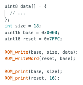
Programming the EEPROM whith Arduino and shift registers
Read
Adding the 6522 Versatile Interface Adapter
I call it the VIA for short. The first task was to define the memory ranges allocated to the ROM and the VIA, and implement the chip-select signals. I opted for the simplest possible solution, minimizing both the number of connections and the amount of additional hardware required.
I then rewrote a simple test program for the VIA and connected LEDs to Port A outputs, but I was unable to get any meaningful result. I carefully checked the wiring, reviewed the documentation, observed the signals with the Arduino, and even attempted to control the VIA directly from the Arduino, but nothing worked. There is clearly something I am missing—or perhaps the VIA itself is defective.
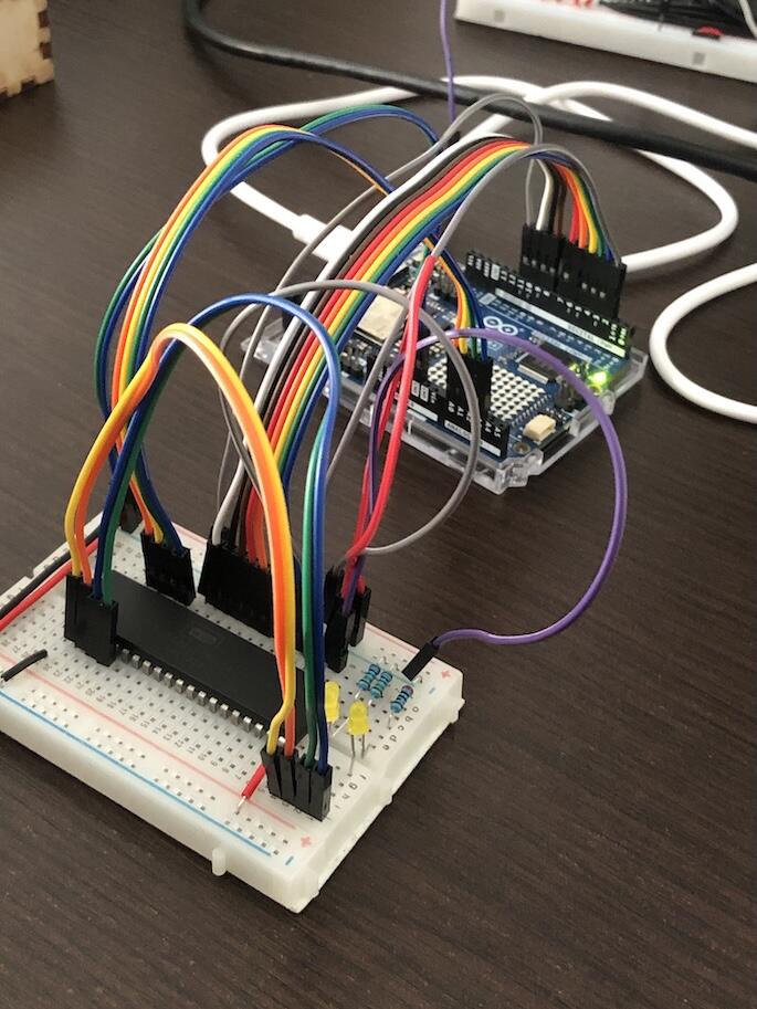
Introducing the 6522 "Versatile Interface Adapter"
Read
Making a D Flip-Flop
To continue making progress despite the issues with the 6522, I decided to implement a D flip-flop from logic gates by following the didcated Ben Eater’s video. It was a bit technical as it involved a fair number of connections. I added two LEDs to visualize the output state—one for the normal output and one for the inverted output.
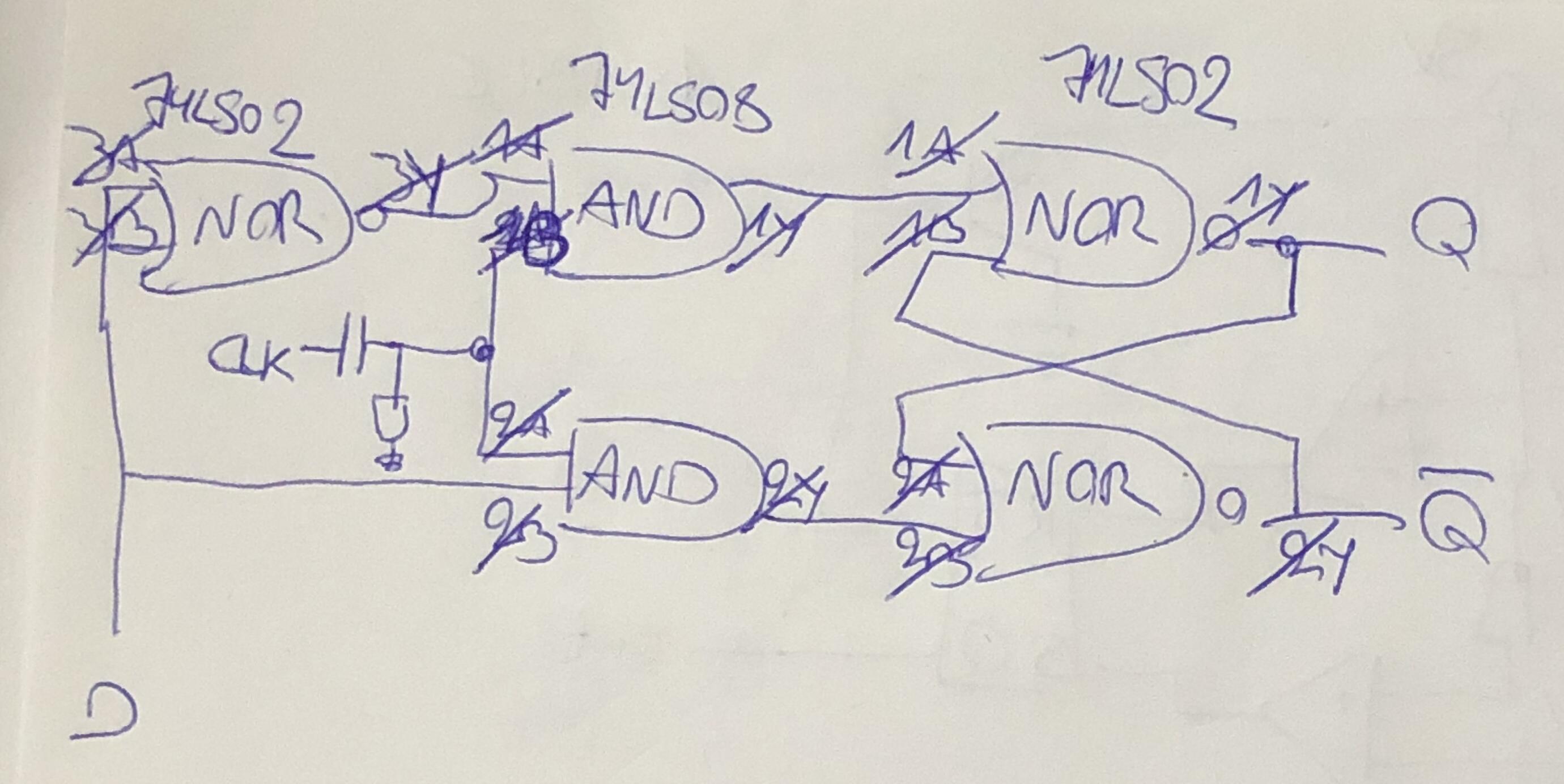
I then connected the flip-flop to the first bit of the data bus in place of the VIA and added logic so that it would only capture data when the correct address was used. I confirmed that the state displayed by the flip-flop matched expectations.
Interfacing a D flip-flop with the 6502 was not part of the original plan, but it turned out to be very rewarding and helped me better understand what may be happening inside chips that communicate over a data bus, such as the ROM or the VIA. I am very glad I took this detour.
Making a D-flip-flop from logic gates and connecting it to the 6502
Read
Future plans
At this point, I have a 6502-based system that I can program to control an LED according to arbitrary logic. It is obviously still very limited, but it is already becoming an interesting system to emulate.
Before moving on to emulation itself, however, I would like to connect a button so that I can create interactive programs. The idea is to use an approach similar to the D flip-flop experiment, but this time build a device capable of placing data onto the bus. I already have a few ideas about how to achieve that.
I use generative AI to write and/or translate the content featured on this website. AI serves only as a tool for productivity and inspiration, I make sure that the final texts always reflect my personal voice and style.