Entry #004 - Jun 5th, 2026
Introducing shift registers
The 6502 is setup on a breadboard and wiring for the EEPROM is ready. The system is now able to read arbitrarily long programs, so I need to be able to program more than 16 bytes of ROM at a time. Until now I was using only 4 address lines because the Arduino does not have enough pins to drive all 15 address lines simultaneously. It is possible to generate more outputs using a component called a shift register.
A shift register produces multiple outputs from a single input bit. Values are sent one at a time and distributed across the output lines in sequence. Each new bit “pushes” the existing data one position further along. Multiple shift registers can be chained together to produce an arbitrary number of outputs. It is also possible to freeze the outputs while shifting in new data to prevent connected devices from seeing the data move from one line to another, which could have undesirable consequences.
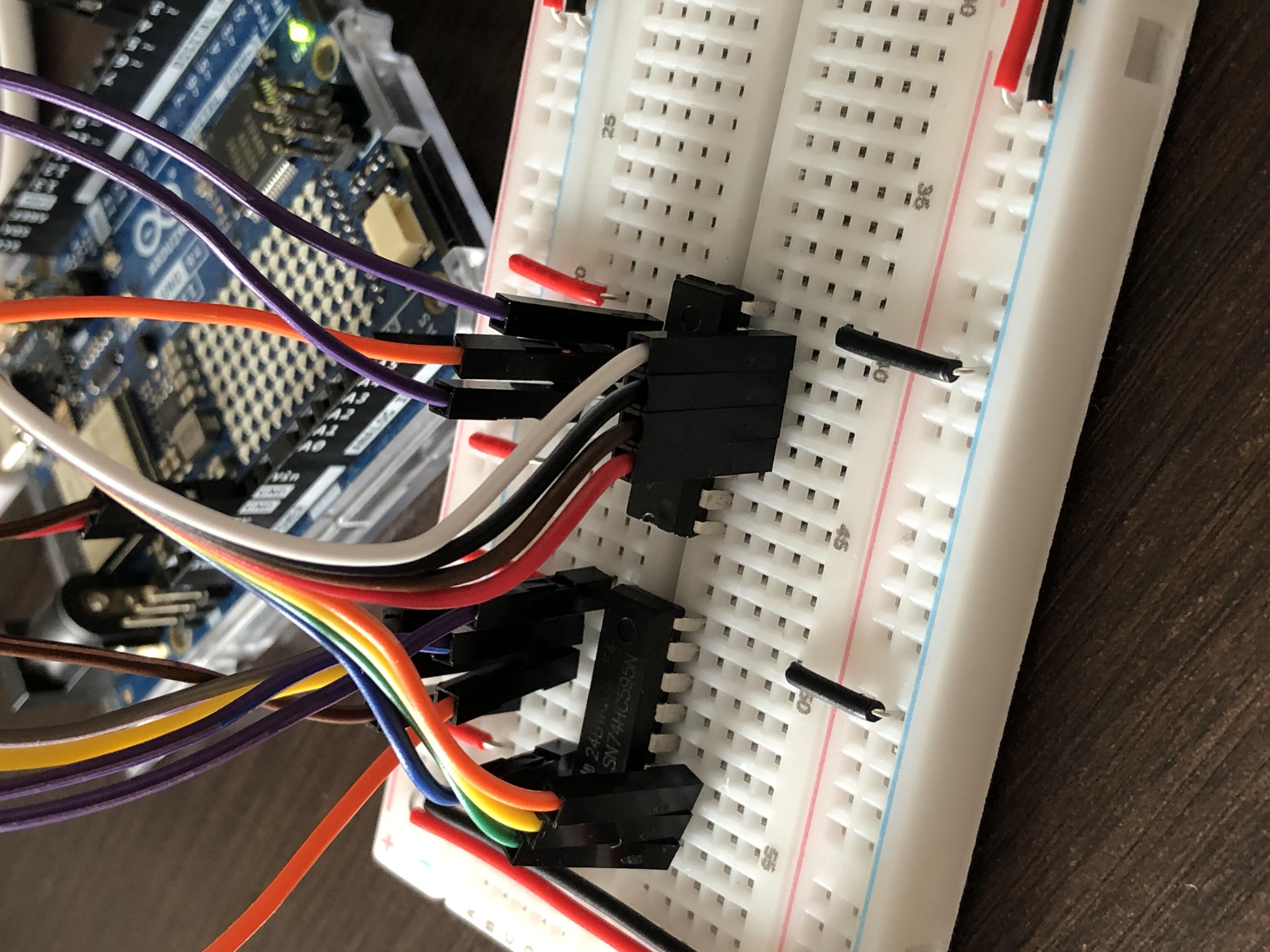
I am using the 74HC595 chip that I have on hand. It is an 8-bit shift register, so two of them are required to control 15 address lines. As usual I start with the basics by building a minimal setup to familiarize myself with its operation. I placed a shift register on a breadboard along with 8 LEDs and their current-limiting resistors.
The 74HC595 has a total of five control signals:
| Signal | Meaning | Function |
|---|---|---|
/OE |
Output Enable | Enables data output |
SER |
Serial Input | Receives input data |
SRCLK |
Shift Register Clock | Shifts the input data into the register |
RCLK |
Storage Register Clock | Updates the outputs to reflect the internal register contents |
/SRCLR |
Shift Register Clear | Clears all stored data |
I connect power and ground, and tie /SRCLR high since I do not plan to use it. I tie /OE low to enable the outputs, and control the remaining signals manually. I start by setting SER high, then pulse SRCLK high and back low. I tried several combinations of values, but the first results were not very conclusive. Either all LEDs were on or all were off. I suspected poor connections, but at one point the first four LEDs were off while the others were on. I realized that my manual manipulation might be generating multiple pulses on SRCLK, causing several bits to be shifted in at once. So I decided to go ahead and move to Arduino control.
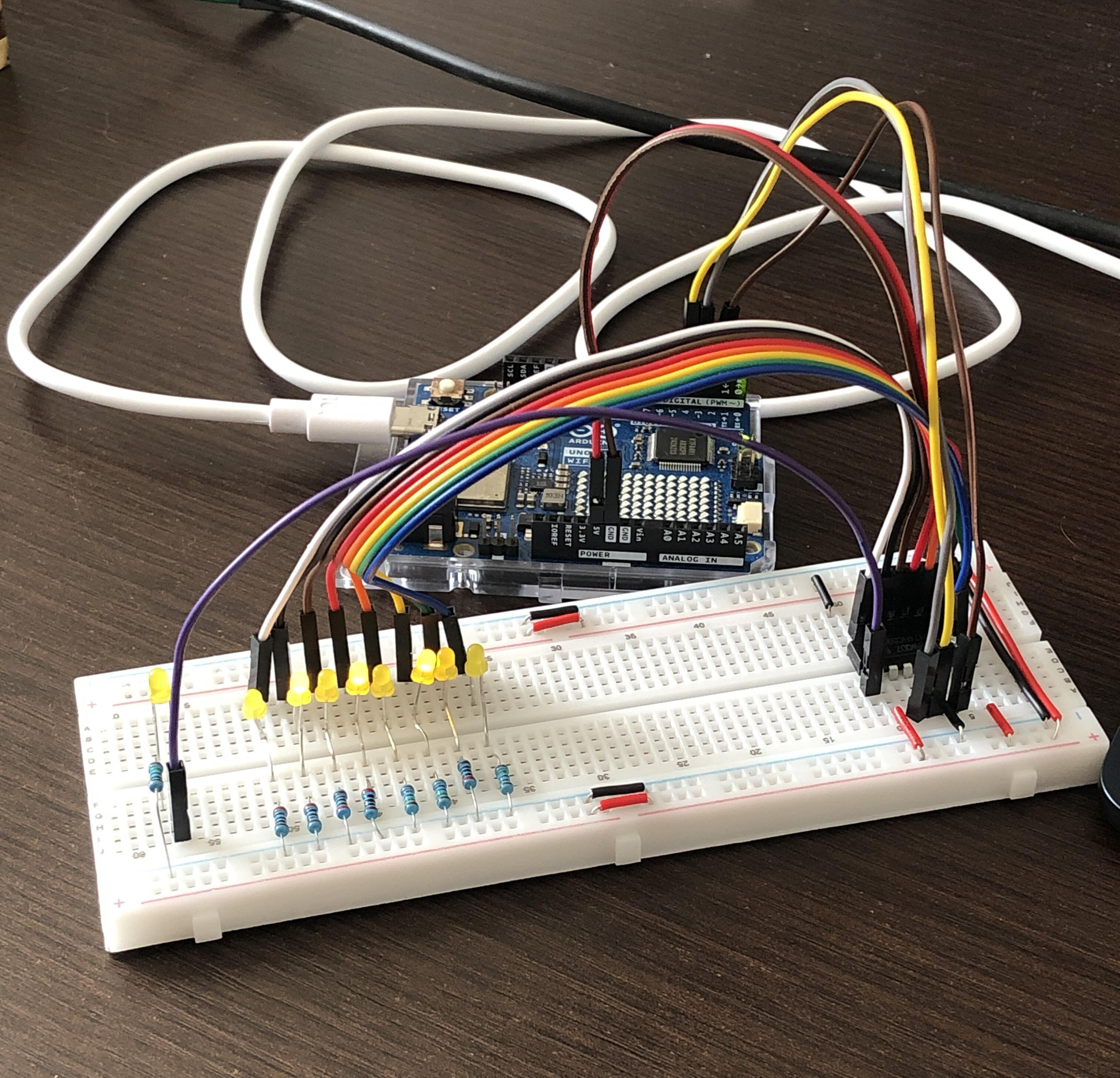
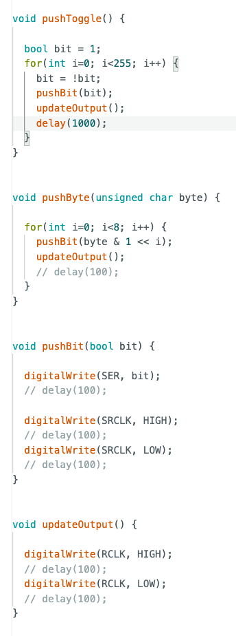
I connect the control signals to the Arduino and write a test program. I start by shifting in one bit at a time, which appears to work correctly. I then write a test function that alternately shifts in a 1 and a 0 with a delay between each operation. It behaves exactly as expected. Next, I test a function capable of shifting in a full byte. Everything works properly. Initially, I had inserted delays, but they turned out to be unnecessary. I also connected an additional LED to display the value of the last bit in the register. Unlike the others, this output always reflects the internal state of the register regardless of whether the outputs are latched, since it is intended to be connected to the next register when chaining multiple registers together.
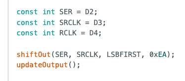
Arduino provides a shiftOut() function that can shift out 8 bits of data. I tested it using the pins I had configured for the serial data and clock signals and verified that it worked correctly. The function shifts the data into the register but does not update the outputs, so I still need to do that manually.
I then tested adding a second register. I place it on the breadboard next to the first one, connect power, /OE, and /SRCLR. Since I cannot add more LEDs, I leave the first four connected to the first four outputs of the first register and connect the remaining four LEDs to the last four outputs of the second register.
At first, nothing worked. The reason was I had forgotten to connect the SER, RCLK, and SRCLK signals from the first register to the second. Once those connections were made, everything worked properly. I tested the setup by shifting in a single 1 followed by a stream of 0s in order to watch the bit move through the registers. As expected, it traveled across the first four LEDs and then, after some time, reappeared on the last four.
Arduino code is available on GitHub.
What’s next
Shift registers make it possible to build a complete ROM programming circuit using an Arduino despite its limited number of I/O pins. Once I can write arbitrarily long programs, I will be able to install an I/O chip that will let me connect peripherals to the 6502, finally making it possible to obtain directly observable results.
I use generative AI to write and/or translate the content featured on this website. AI serves only as a tool for productivity and inspiration, I make sure that the final texts always reflect my personal voice and style.