Entry #001 - Jun 1st, 2026
First steps with the 6502
I play video games on emulators and I understand the basic principles of emulation, but I want to learn more and get my hands dirty. I’d like to know how to write a Game Boy emulator, and it’s probably doable with enough patience, but I like to start from the basics. That is why I set out to build a simple, programmable hardware system and write an emulator for it. This will allow me to start slow and discover the fundamental principles of emulation, adding complexity at my onw pace later on.
I chose to use the 6502 processor and its 6522 interface, taking reference from Ben Eater’s excellent video series dedicated to those components. The 6502 was the CPU of many consumer devices in the 1980s, notably the Apple II, Commodore 64 and Atari 2600. It is a relatively simple microprocessor, ideal for beginners. Modernized versions are still in production today, and there’s a large community of enthusiasts.
Being a microprocessor, the 6502’s main function is to execute instructions. Unlike a microcontroller, it has no internal memory or peripherals. It interacts with the outside world via a data and address bus, on which it can read and write data. The instructions to be executed, the data to be processed, and the output data all pass through the bus. Generally, a memory containing the program and working data is connected to the bus, along with peripherals such as a display, a sound card, etc.
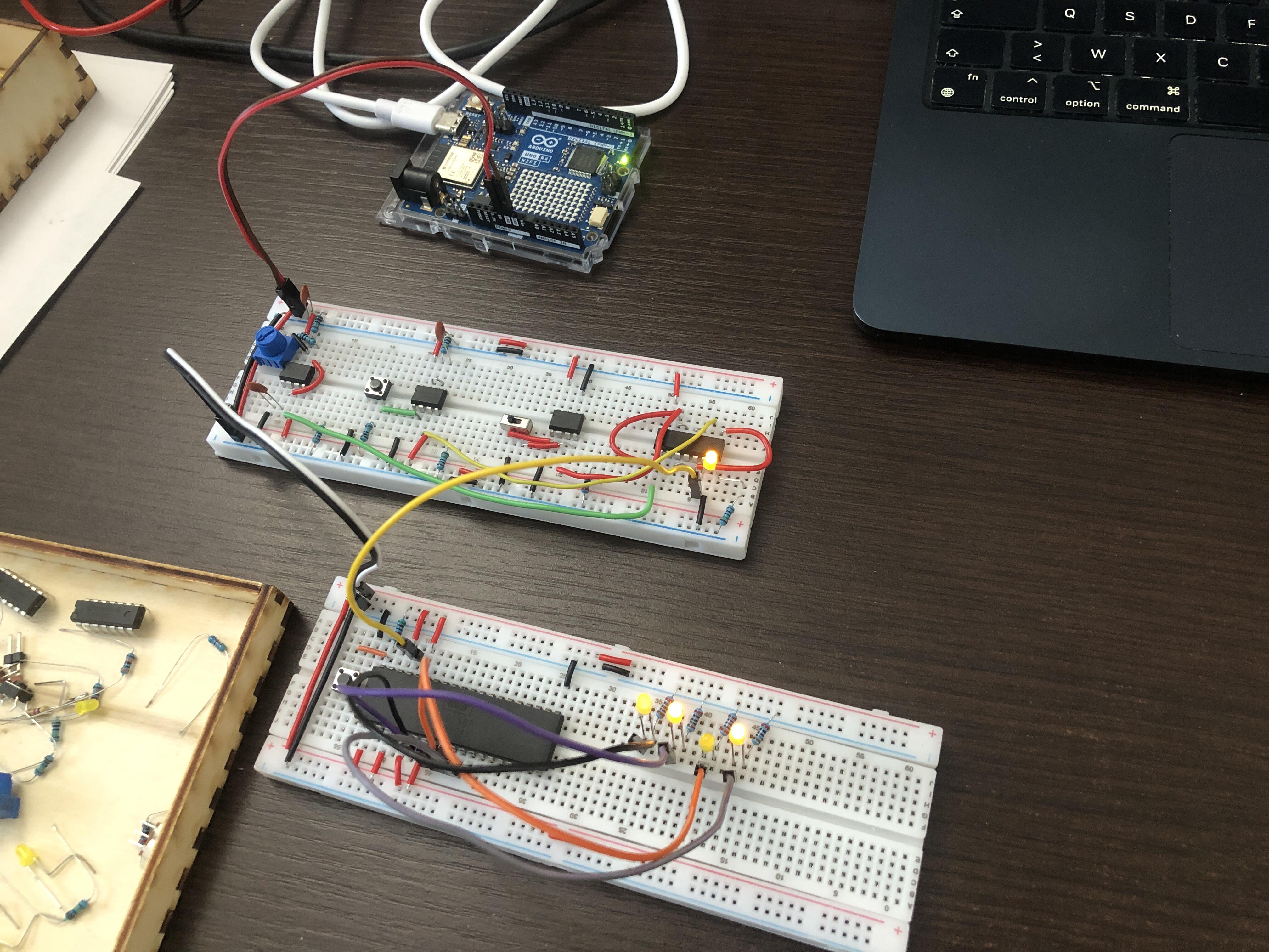
I begin by mounting the 6502 on a breadboard, connecting the power supply and basic control signals, and adding a reset button. The clock signal is generated by a module based on a 555 timer circuit that I built previously following Ben Eater’s videos on that topic. I’m using my Arduino as a power source and for making observations afterward.
To verify that something is happening in the processor, I connect the four least significant bits of the address bus to four LEDs, and they indeed show activity. I also connected the data bus lines directly to the power supply or ground using resistors so that every time the CPU reads data from the bus, it retrieves the value 0xEA, which corresponds to the NOP (“No Operation”) instruction. When observing the address lines, we see a count, which corresponds to the CPU reading instructions one after another from memory.
I then connected the address lines to the Arduino along with the clock signal and wrote a simple program to read and display the data at each clock tick via an interrupt. Ben Eater uses an Arduino Mega to observe all 16 address lines and 8 data lines, but my Arduino Uno doesn’t have enough pins to allow me to observe all the lines, so I focused on just the 4 least significant bits of the address.
When the processor starts or is reset, it looks for the address of the first instruction to execute. To do this, it reads a 16 bit address from addresses 0xFFFC and 0xFFFD, then starts fetching instructions from that address. Since I’m only observing the last 4 bits of the address, I expect to see the values C and D, which correspond to the binary values 1100 and 1101 respectively. When I press the reset button, I do indeed see these addresses. Since the data bus is wired to return 0xEA, the CPU will start reading instructions from address 0xEAEA. The binary value A is 1010, and it’s indeed the first address we see after C and D. Very cool!
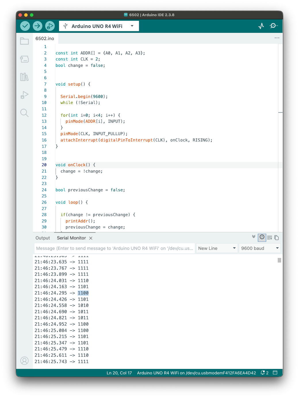
Arduino code is available on GitHub.
Next Steps
The next step is to provide the CPU with dynamic data based on the address it requests, to form a meaningful program. This is typically done by a memory chip. But Arduino can also be used.
I use generative AI to write and/or translate the content featured on this website. AI serves only as a tool for productivity and inspiration, I make sure that the final texts always reflect my personal voice and style.