Entry #005 - Jun 6th, 2026
Programming the EEPROM whith Arduino and shift registers
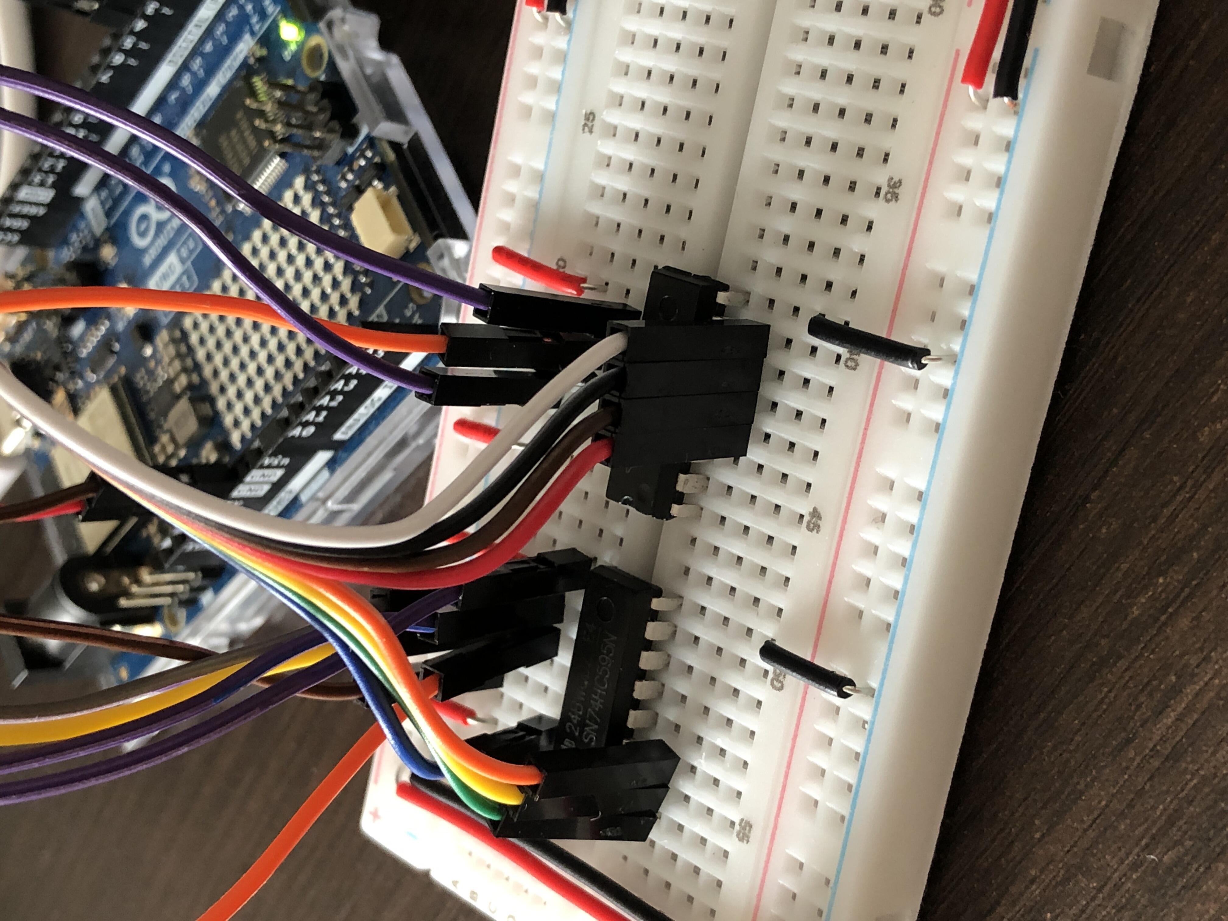
The shift registers are ready to output the 16 address lines needed to program the EEPROM. I set it up on the breadboard, replacing the LEDs. I connect the power supply and force /CE to 0. I then connect the 15 address lines to the outputs of the shift registers, in order starting with the least significant bits. On the last output of the last register, I connect /OE. This gives the following mapping:
| Register | Output | ROM Input |
|---|---|---|
| R1 | QA | A0 |
| R1 | QB | A1 |
| R1 | QC | A2 |
| R1 | QD | A3 |
| R1 | QE | A4 |
| R1 | QF | A5 |
| R1 | QG | A6 |
| R1 | QH | A7 |
| R2 | QA | A8 |
| R2 | QB | A9 |
| R2 | QC | A10 |
| R2 | QD | A11 |
| R2 | QE | A12 |
| R2 | QF | A13 |
| R2 | QG | A14 |
| R2 | QH | /OE |
I connect /WE and the data lines directly to the Arduino as before, and I’m ready to start coding. I use Ben Eater’s video as a reference, but I try to do as much as possible on my own and experiment in my own way. I reuse the code that was previously used to program the ROM and modify the setAddr() function so that it now uses the shift registers, and I add a parameter for the value of /OE.
The shifting logic is a bit technical. The goal is to push the address bits into the registers in the correct order so that the right bits ultimately appear on the correct ROM address lines, as well as the /OE bit. I use the Arduino shiftOut() function, and although it can be passed a number larger than 8 bits, it only shifts out the first 8 bits. Therefore, the address must be split into two 8-bit chunks and I need to call the function twice. An additional parameter determines the order in which the bits are shifted out:
| Option | Meaning |
|---|---|
MSBFIRST |
Most significant bits first |
LSBFIRST |
Least significant bits first |
If we shift out 1110 1010 (0xEA):
- With
MSBFIRST, the bits are shifted in this order:1,1,1,0,1,0,1,0 - With
LSBFIRST, the bits are shifted in this order:0,1,0,1,0,1,1,1
When shifting out 16 bits, the first bit shifted will end up on the last output line, while the last bit shifted will end up on the first. In our case, we therefore need to shift the most significant bits first.
Here is what I initially wrote:

Reading
I try reading data from the ROM, but it doesn’t work. I can’t retrieve the data that was previously programmed. Everything is wrong. I immediately suspect a bug in the code above as it is the most tricky part, but nothing obvious stands out. So I extract the logic into a test function and print the results to the console while forcing the input values. I quickly discover that it is not at all doing what it is supposed to do. First, there is a typo in the second line: there should be a single & instead of &&, since we want a bitwise AND, not a logical AND. Second, for the /OE bit to end up in position 8 (counting from 1), it needs to be shifted by 7 bits rather than 8. In the end, I followed Ben Eater’s approach and simply used the value 0x80 directly. It makes the code a bit more readable.
Here is the corrected version that works:

Arduino code is available on GitHub.
Writing
Next, I test writing, and at first it doesn’t work reliably. I try writing a single byte, multiple bytes, and running the same tests repeatedly. Sometimes it works, sometimes it doesn’t. I review the code carefully and everything looks correct. Puzzled, I turn to ChatGPT. I paste the code without any question so as not to influence the analysis and see what it notices on its own.
It points out that a delay is missing after the /WE pulse. That’s interesting because I hadn’t thought about it. The write operation does not occur when /WE goes low, but when it returns high, and the ROM needs a bit of time to actually store the data. So I add a delay() after digitalWrite(WEB, HIGH), and at first it seems to work. Then it starts failing again.
I write a test program that continuously writes and reads while cycling through values and addresses. I notice that some writes succeed and others don’t, with no obvious pattern. I let the program run and inspect the wiring. I notice that the results seem to change when I move the /WE wire. I therefore suspect a bad connection. I replace the wire and things immediately seem more reliable.
I run more tests and confirm there is a net improvement. However, one issue remains: whenever I write a sequence, the first byte is always written incorrectly. Among ChatGPT’s earlier observations, there was a note regarding the order of pinMode() and digitalWrite() calls that I had dismissed because I followed Ben Eater’s advice and called digitalWrite() first to ensure that the pin never briefly goes low during setup, which could trigger undesired writes. Ben explains that although it seems counterintuitive, it works and is the correct way to do it.
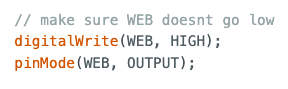
In my case, however, since it is always the first write that fails, I strongly suspect that /WE is not actually left high at startup as expected. I therefore add another digitalWrite() after pinMode(), and the problem disappears.
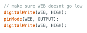
I also add another digitalWrite() when generating the pulse to ensure that we always start from a known high state.
To validate my observations, I quickly connect /WE to an LED and confirm that after calling digitalWrite() and pinMode() in that order, the LED does not light up. It only turns on after an additional digitalWrite().
I don’t have an explanation for why it worked for Ben Eater but not for me. Perhaps differences between Arduino models.
This experiment also clearly shows that the signal goes low when I reset or reprogram the Arduino, which makes me wonder whether this could trigger unwanted writes, since the ROM remains active during that time. Assuming all pins go low, that would include /OE, and no write operation is possible while /OE is low, so everything should be safe. To be extra cautious, one could connect /CE to the Arduino through an inverter instead of physically tying it low on the breadboard. That way, the ROM would only become active once the Arduino is ready. Everything works fine as it is, so I won’t change it for now, but it’s the kind of detail that can come back to cause trouble when you least expect it.
Optimization
Now that everything works correctly, I can try speeding things up. Up until now I had been using delay(100) everywhere just to ensure everything worked and to give myself time to observe what was happening. But if we want to read or write any significant amount of data, this is unnecessarily slow.
In an attempt to do things properly, I go through the datasheets of the various components to determine the minimum timing requirements. For the AT28C256 EEPROM, the maximum delay between an address change and valid output data is specified as 150 ns. I perform a quick calculation based on the Arduino clock speed. My Uno R4 WiFi runs at 48 MHz, corresponding to a clock period of approximately 20 ns. So I add a delayMicroseconds(1). I test and it works. Thinking about it, a high-level function such as digitalWrite() probably takes many clock cycles, so everything should work without any delay at all. Something to test next time. Likewise, I replace the delay(100) used for the /WE pulse with delayMicroseconds(1) without any issues.
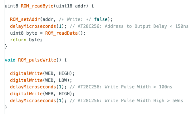
For the 74HC595 shift registers however, the datasheet indicates that a latch pulse width of roughly 1 µs should be more than sufficient. But surprisingly, that does not work in my setup. I test various values and determine that 10 ms is the minimum delay that works reliably. That leaves me puzzled. At that speed, programming the entire ROM (roughly 32,000 addresses) would take at least 320 seconds, that is more than five minutes.
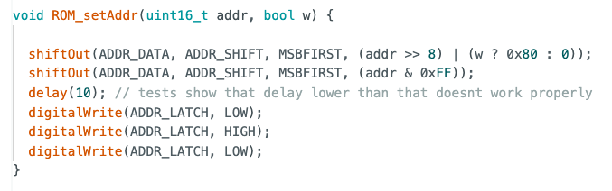
I ask ChatGPT, it isn’t particularly useful but it does help me determine that the issue is not the pulse duration itself, but the delay preceding it. Here is the best code I was able to get:
It might be a breadboard issue, but Ben Eater’s setup works perfectly without any delay. Perhaps my cheap AliExpress breadboards are of too poor quality, or maybe some contacts are unreliable. I don’t really believe that, and even ChatGPT seems skeptical:
Even a terrible breadboarded HC595 setup should not require that.
And when I think about it, the delay occurs between shifting data into the registers and latching it to the outputs. No long-distance signal transmission is involved. Everything happens inside the shift registers themselves, so the breadboard should not matter. I still don’t have an explanation.
Cleanup and improvements
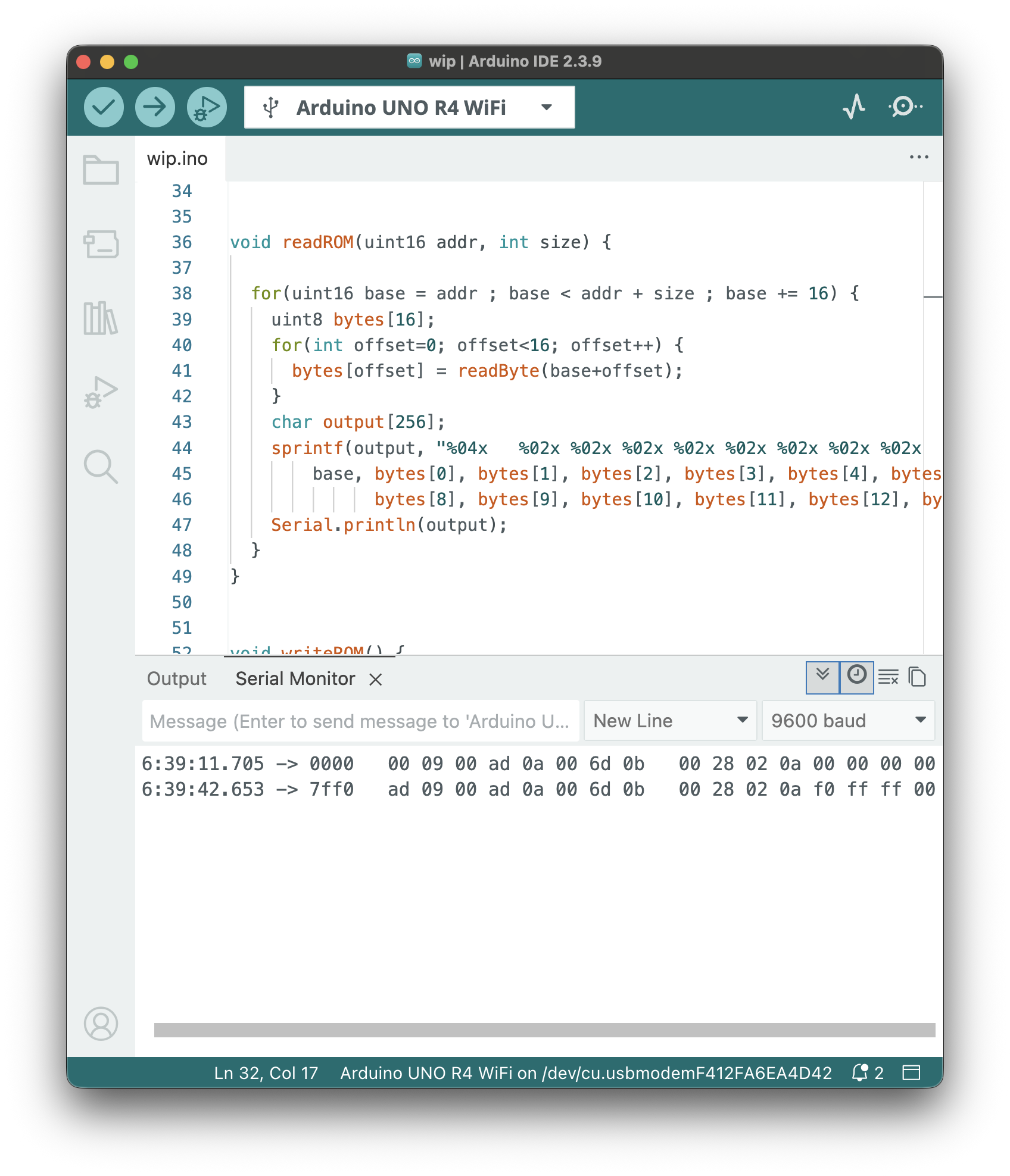
Now that I can read and write (mostly) fine, I clean up the code a bit. I rewrite the print() function so that it displays rows of 16 bytes instead of a single address at a time, and I make it possible to pass any arbitrary starting address, even if it is not aligned on a 16-byte boundary.
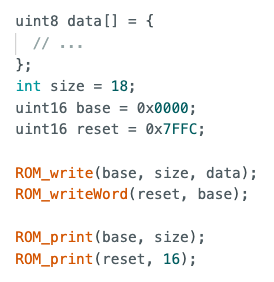
I also add a function to write two bytes at once at a given address. Thanks to these changes, I can now write things like this:
For now, the code uses a fixed delay between writes, but the ROM also provides a way to detect when a write operation has completed. That would allow the next byte to be sent as soon as the memory is ready. Implementing that feature would be an interesting technical exercise, but in my case it would not improve programming speed because the delay associated with the shift registers is currently the dominant bottleneck by far. Still, it’s an idea worth keeping in mind if I ever find a solution to that problem.
Arduino code is available on GitHub.
What’s Next
Now that I can write arbitrarily long programs into memory, I can start installing the I/O chip that will allow peripherals to be connected to the 6502 and finally make CPU activity visible without external instruments.
I use generative AI to write and/or translate the content featured on this website. AI serves only as a tool for productivity and inspiration, I make sure that the final texts always reflect my personal voice and style.