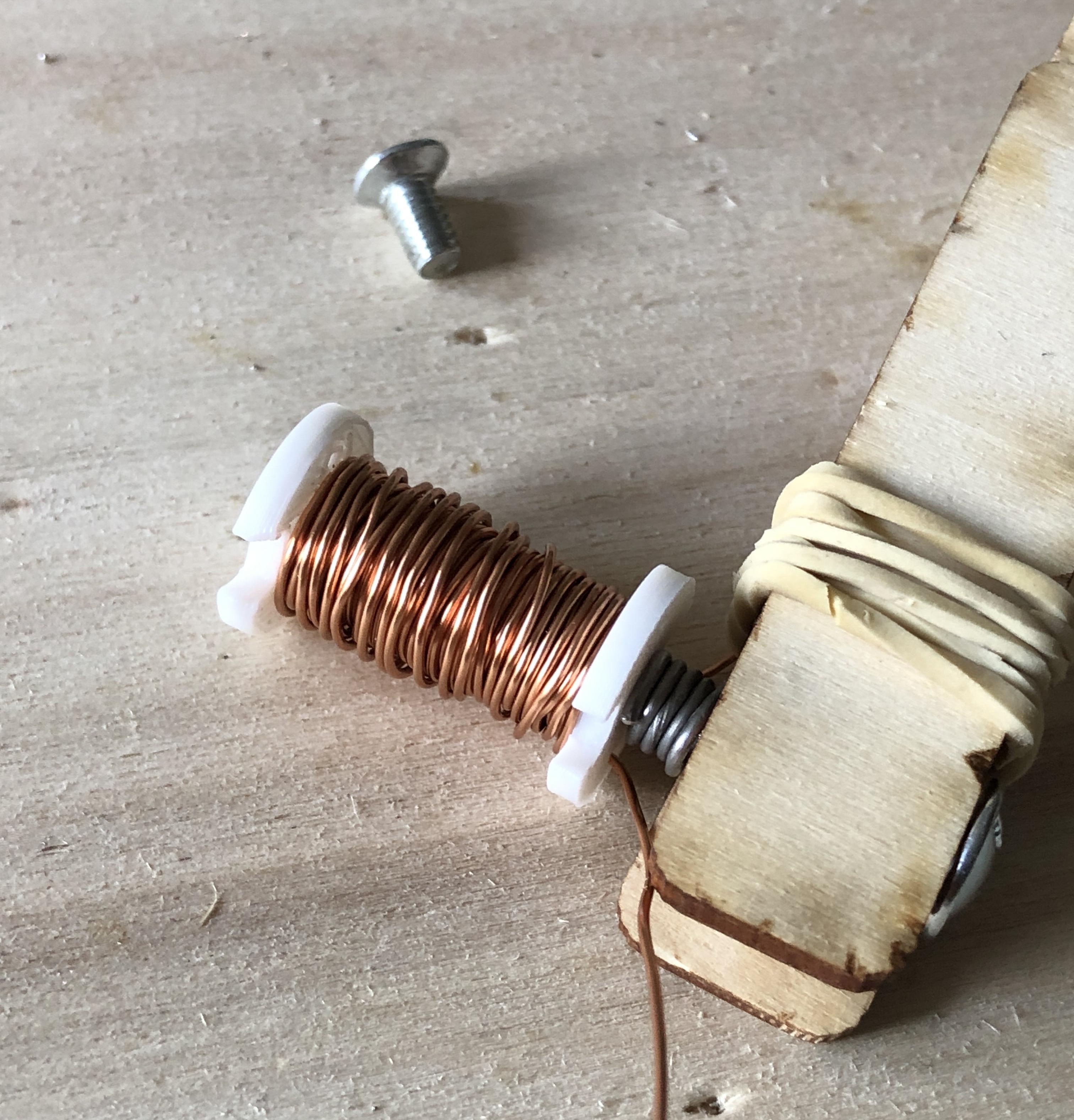
Jun 19th, 2026
First attempt at building a solenoid
Introduction
I would like to gain a deeper understanding of how electric motors work, particularly their control electronics. I studied engineering and understand the basic principles, but theoretical courses only provide a limited understanding of how things actually work. I want to develop both a detailed understanding and practical experience in this area.
To help achieve this goal I decided to build a brushless DC motor (BLDC) from scratch. The first step is to create windings capable of generating a magnetic field, also known as a solenoid. As usual I want to start from the fundamentals and explore the basic principles behind coil construction.
My initial objective is to build a simple coil and observe the presence of a magnetic field when it is powered. Later, I plan to assemble multiple coils and develop control logic to rotate a moving part, laying the groundwork for a motor.
Preparations
I begin by doing some research to establish a plan of action. I understand the general idea, but the details are still unclear.
The first topic is copper wire. Although it appears bare when looking at a coil, it is actually coated with an insulating enamel layer. Bare wire would not work because the goal is for current to flow through every turn of the coil. If the wire were bare, since all the turns touch each other, the current would take the shortest path instead of flowing around the axis, which is necessary to create the desired magnetic field.
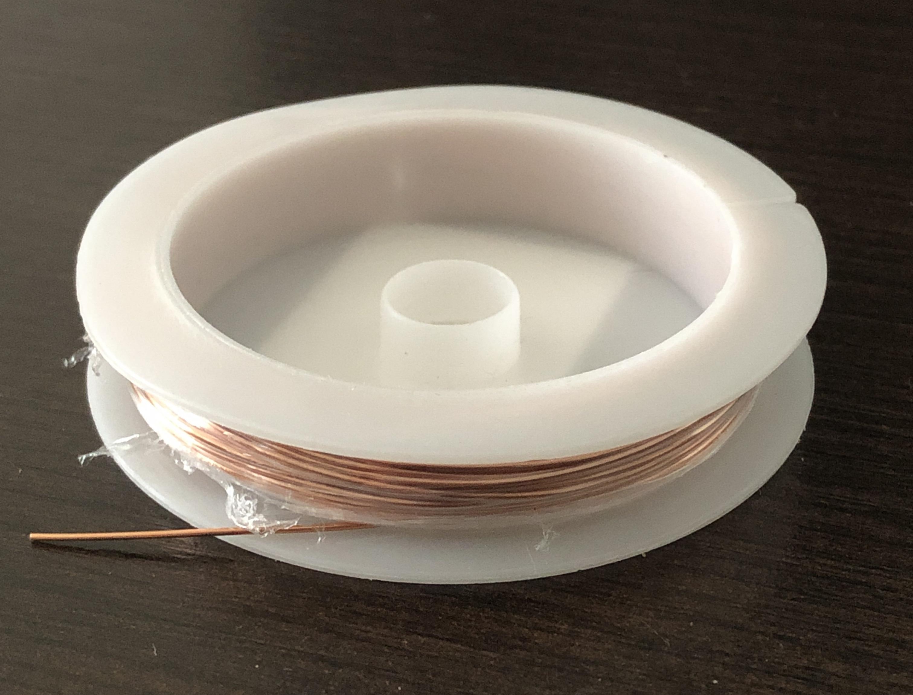
The wire is available in different diameters, ranging from very thin to very thick. I chose a 0.6 mm diameter wire (AWG22), which seemed like a good compromise. In hindsight, a thinner wire might allow more turns to be wound more easily, which could be advantageous.
I then wondered how I should power the coil because, fundamentally, it looks a lot like creating a short circuit, which seemed dangerous. ChatGPT helped me understand that I could place a resistor in series to limit the current. That is perfect because based on the maximum current I am comfortable with, I can determine a resistor value to insert into the circuit and limit the current to that value.
I now want to identify the parameters that determine magnetic field strength and get a sense of the possible orders of magnitude. The magnetic field strength along the axis of the coil is given by the following equation:
| Symbol | Description | Unit |
|---|---|---|
| B | Magnetic field strength | Tesla (T) |
| I | Current flowing through the coil | Amperes (A) |
| N | Number of turns around the coil | - |
| R | Coil radius | meters (m) |
| μ0 | Vacuum permeability | Henry per meter (H/m) |
A quick calculation shows that with a coil radius of 1 cm, a current of 0.2 A, and 10 turns, the resulting magnetic field is about 120 μT. That doesn’t tell me much because I don’t yet have an intuition for the magnitudes. To help, I looked up the magnetic field strength produced by common permanent magnets and found values around 0.5 T. We are still quite far from that.
Continuing my research, I found that it is possible to dramatically increase the magnetic field by using an iron core. In that case, the formula becomes:
| Symbol | Description | Unit |
|---|---|---|
| μr | Relative permeability of the core material | Henry per meter (H/m) |
The relative permeability of iron depends on its exact composition but can typically reach around 5000. In the previous example we can then increase the magnetic field from 120 μT to 600 mT, or 0.6 T, simply by adding an iron core. Not bad.
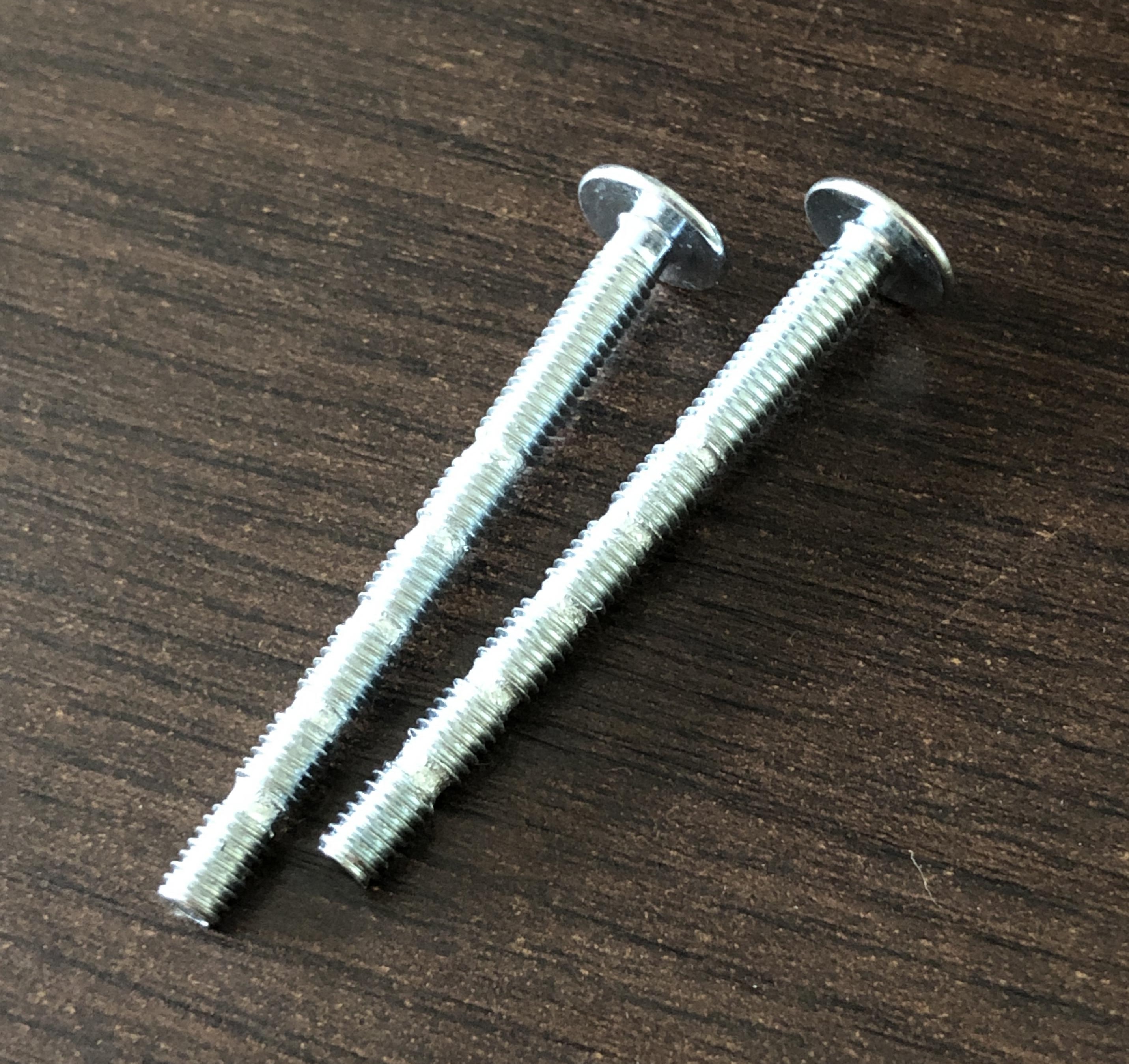
I looked through my workshop supplies and found some screws left over from my woodworking projects. I tested them with a magnet and they were attracted. Perfect. Their diameter is approximately 4 mm, which should slightly increase the magnetic field compared to the calculations from earlier. I’m not sure of their exact composition, however, so there is some uncertainty regarding their relative permeability.
I then reviewed the safety aspects. Since I can limit the current, there should be no danger from that side. However, heat generation could potentially become an issue. The power dissipated in the coil can be calculated from the supply voltage and current:
| Symbol | Description | Unit |
|---|---|---|
| P | Power dissipated by the coil | Watts (W) |
| U | Voltage across the coil | Volts (V) |
| I | Current flowing through the coil | Amperes (A) |
| R | Total circuit resistance | Ohms (Ω) |
ChatGPT provided some rough guidelines. A few watts should not pose a danger for a short duration, but tens of watts would heat up very quickly.
I kept this in mind and created a spreadsheet gathering the physical and electrical parameters of the coil. It calculates current, magnetic field strength, and dissipated heat. This allows me to experiment with different parameters and find values I am comfortable using for the first tests.
Since the screw composition is uncertain, I defined a range for the core permeability and aimed for currents below 100 mA. With ChatGPT’s help, I estimated the coil resistance would be around 10 Ω, to be measured once a coil was built. I concluded that 100 turns and a 1 kΩ resistor would be a good starting point.

Making the first coil
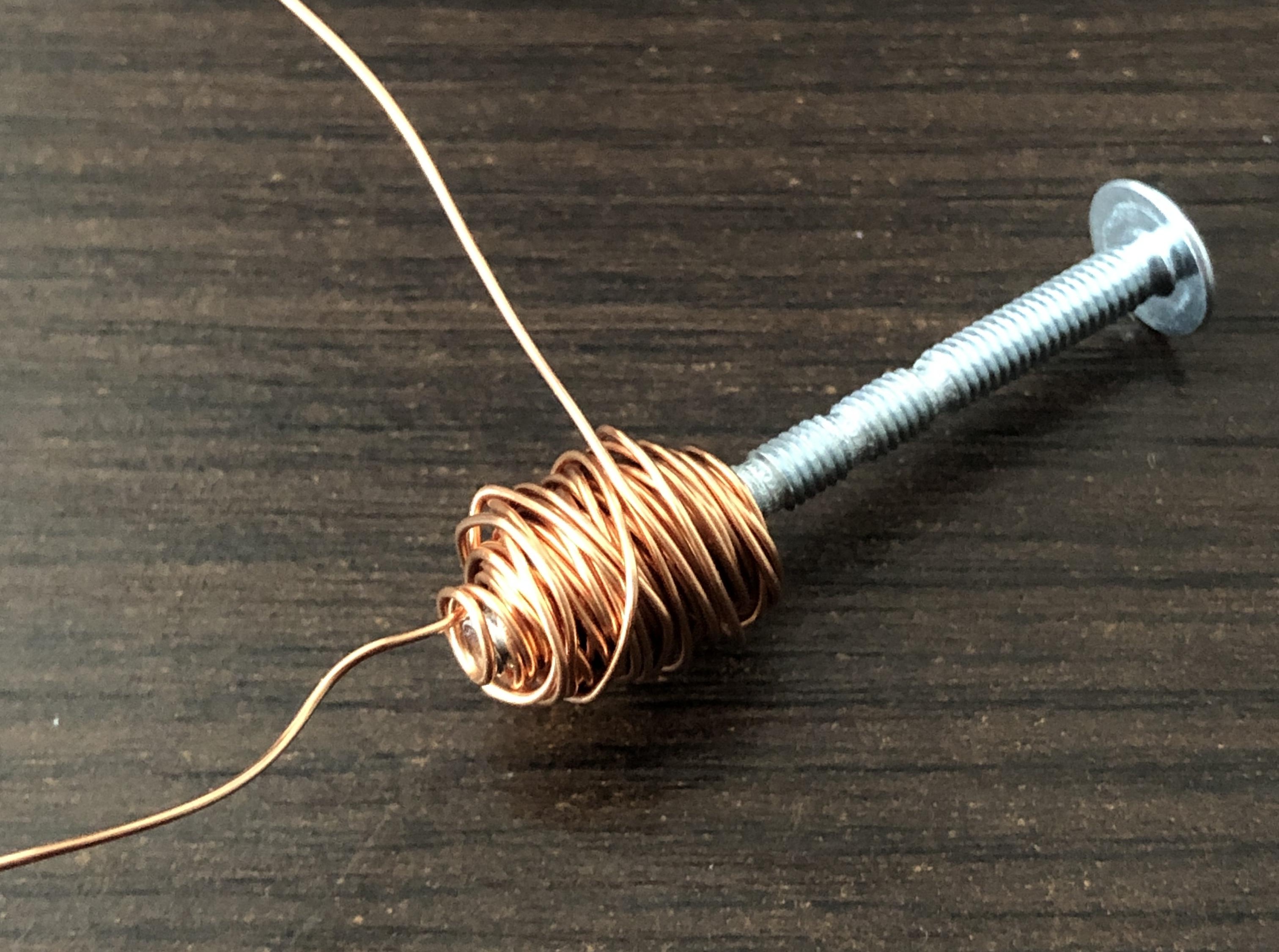
I attempted a first coil by winding about one hundred turns around a screw. I restricted the winding area to one end of the screw to leave a section that could be easily held. The wire turned out to be fairly stiff, making it difficult to produce a neat winding, especially on the outer layers.
Once the coil was ready, the first challenge was removing the enamel at the wire ends so electrical connections could be made. I researched the topic and found two main methods: mechanically scraping it with a blade or heating and tinning it with a soldering iron.
I tried the soldering iron method. I placed the hot iron on the wire, but at first nothing much happened. I persisted, rubbing the wire with the iron, but the effect was not obvious. When I added solder, it initially beaded up without adhering. After some effort, the wire turned silver. I thought a thin layer of solder had finally deposited, but I wasn’t sure whether the enamel underneath had actually been removed. I repeated the process on the other end and then checked continuity with a multimeter. Nothing.
I then tried scraping the wire but struggled to find an effective technique. The wire is small and relatively soft, making it difficult to scrape without the blade catching. After several attempts, I thought I had removed some enamel. I tested continuity again, but still nothing.
I asked ChatGPT, which confirmed that these are indeed the main methods. It mentionned chemical processes also exist for industrial applications.
At that point, I decided to experiment on a separate piece of wire instead of repeatedly attacking the coil terminals. I was somewhat concerned about damaging my good soldering iron, which I use for precision soldering, and I didn’t want to leave it overheating unnecessarily. So I dug out the inexpensive soldering iron I used before, which also has a larger tip. This was a job for that one.
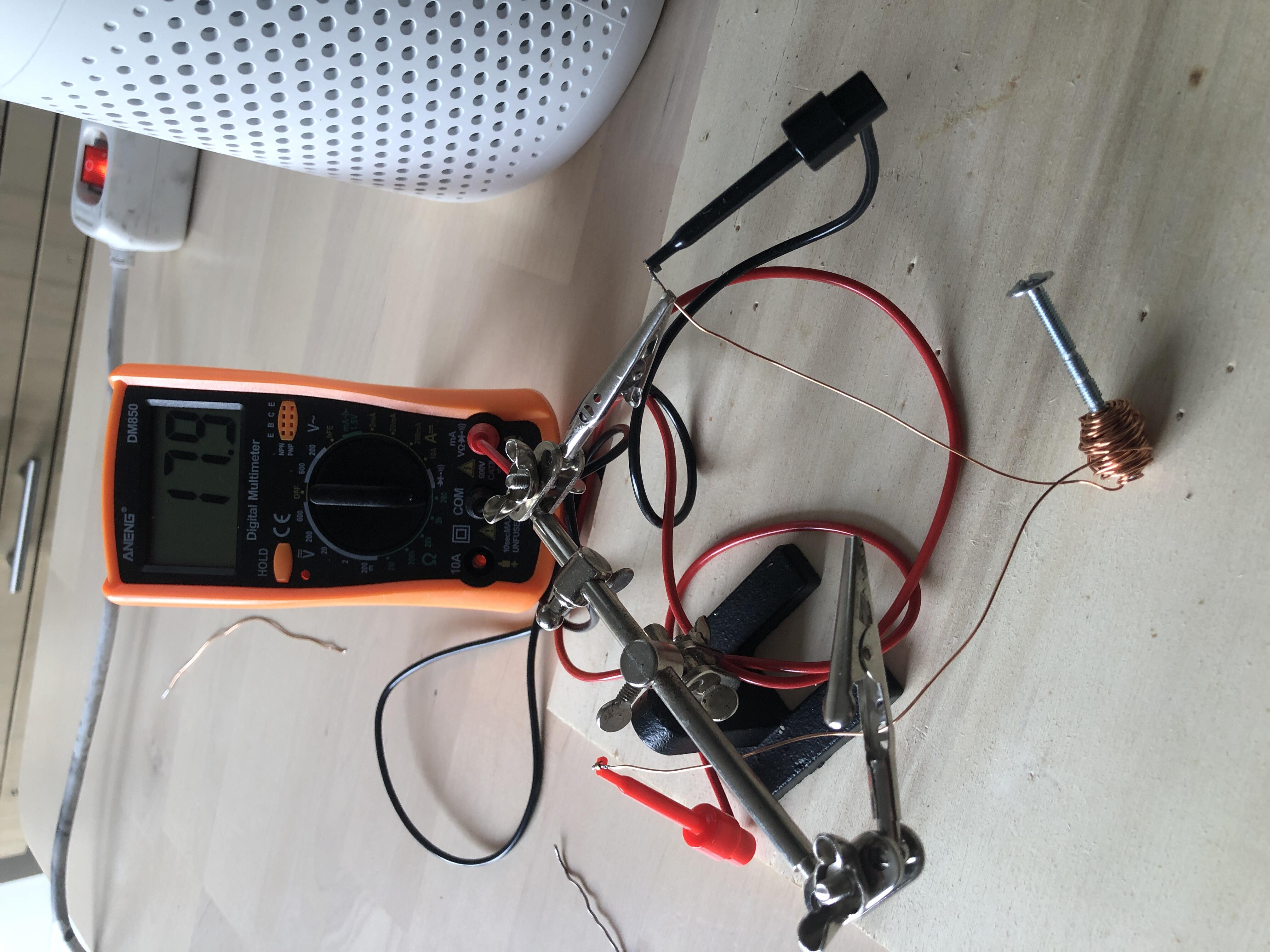
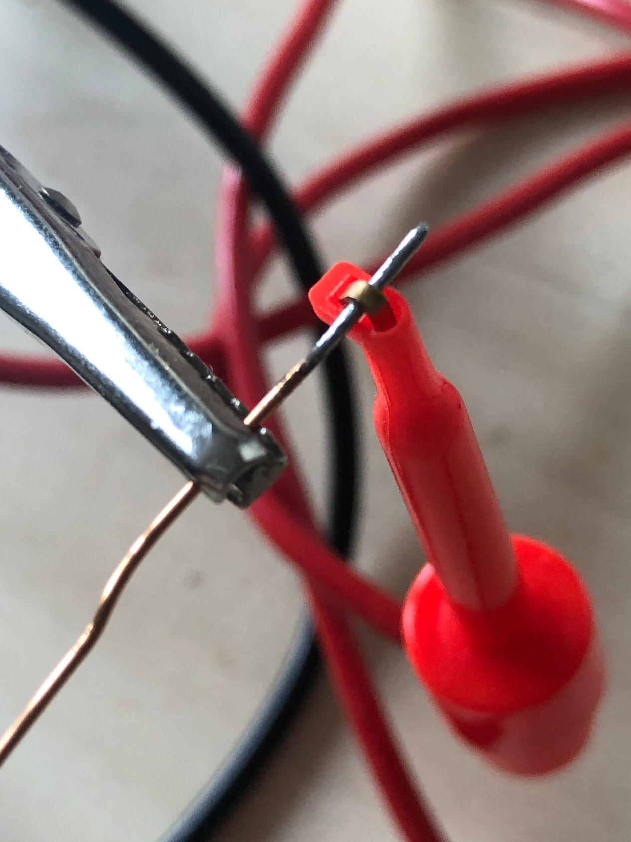
After enough heat and solder, I finally got a result. I tested continuity and this time it worked. I then repeated the process on the coil, and current flowed successfully. Measuring the resistance gave a value close to 20 Ω. That was consistent with expectations and therefore encouraging.
First test
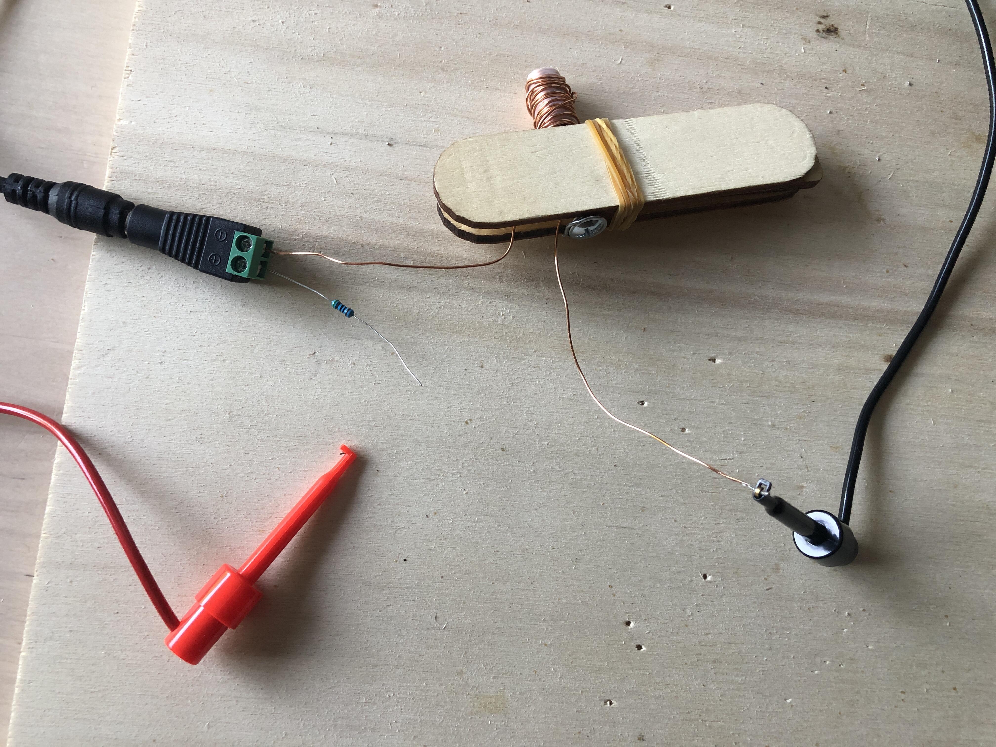
I worked on a wooden board to protect the table in case of overheating. I connected the power supply through an extension cord to reduce any risk to my computer equipment in case something went wrong. Since excessive heat tends to be invisible until its too late, I wrapped a piece of PLA filament and some solder around the screw to act as warning signals.
I connected one end of the coil to the power supply and a resistor to the other end. I wanted to monitor the current, so I used the multimeter to complete the circuit. As a bonus, this provided a convenient way to connect and disconnect the circuit without soldering or permanent connectors.
After verifying everything, I briefly closed the circuit. The measured current was approximately 23 mA, matching the calculations. I tried attracting a small screw, but nothing happened. No detectable attraction at all.
Making a second coil
During the previous experiments, I accidentally received several small electric shocks when touching the screw. This suggested electrical contact between the coil wire and the screw, which should not happen. I confirmed with a multimeter that there was indeed continuity between the coil and the screw, and I suspected this was affecting the coil’s performance.
I know that the enamel coating is fairly fragile and can be damaged easily, creating unwanted electrical contacts. If the wire is damaged in multiple places, short circuits can occur within the coil itself, which is definitely not what we want. Ideally, I should rebuild the coil using a fresh piece of wire, but before consuming more resources (which are limited), I decided to experiment further and improve my winding technique.
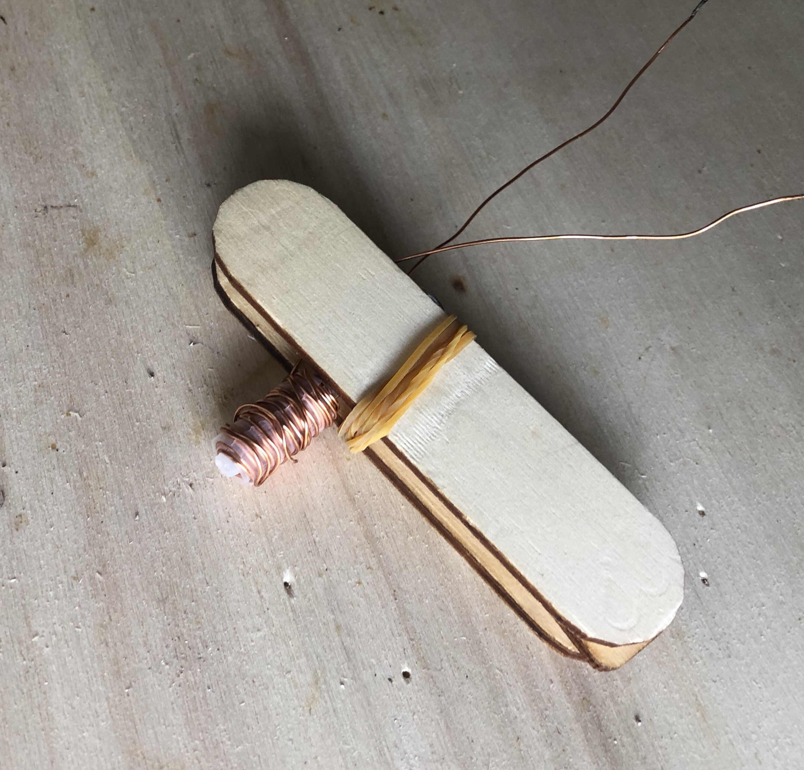
I rewound the coil using the same wire as before, trying to make the winding more uniform. This time I also wrapped a piece of tape around the screw to provide insulation. I improvised a wooden holder to make the screw easier to handle and to avoid touching it directly in case there was still electrical contact or in case of overheating.
The holder greatly improved the winding process, and I obtained a much neater result. The goal is to place each turn neatly against the previous one, but I found that once the first layers were completed it became difficult to distinguish between them. To help with this, I added tape between some of the layers.
Since the wire had already been used during the first attempt, it was now deformed in places, which made winding somewhat more difficult, especially toward the end. Nevertheless, I managed to finish the coil, and it already looked much cleaner than the first one.
I tested continuity between the coil and the screw and confirmed that they were properly isolated. I then measured the resistance, but the multimeter reading would not stabilize. I had already encountered this issue when I first started measuring resistances, and I’m not really sure what causes it. Hopefully it is not a problem with the multimeter itself.
I powered the coil, but there was still no visible sign of magnetism.
Making a coil winding machine
Before rebuilding a coil with fresh wire, I wanted to improve my winding technique. And to do that I needed some winding tools.
I spent some time looking at how other people do it on YouTube. I discovered that dedicated winding machines exist, and that some people have even built their own at home. For now I wanted to keep things as simple as possible. I can always build something more sophisticated later.
The basic requirement is to be able to keep the wire under tension without hurting my fingers by holding the screw directly, while also being able to guide the wire precisely. This means I need a support capable of holding the core while allowing it to rotate with sufficient torque.
For a while, I considered a mechanism that would rotate the screw directly. Then I thought it might be a good idea to place a plastic sleeve around the screw, both to provide insulation and to wind the wire around it. At that point, it would no longer be necessary to rotate the screw itself, only the plastic spool.
I spent some time thinking about it and trying to visualize a mechanism, but I couldn’t quite picture all the details. I opened my CAD software anyway, hoping that the design would become clearer as I drew it. I created an initial version, and it did indeed help me get a better picture. At that point I started over toward a clear the goal.
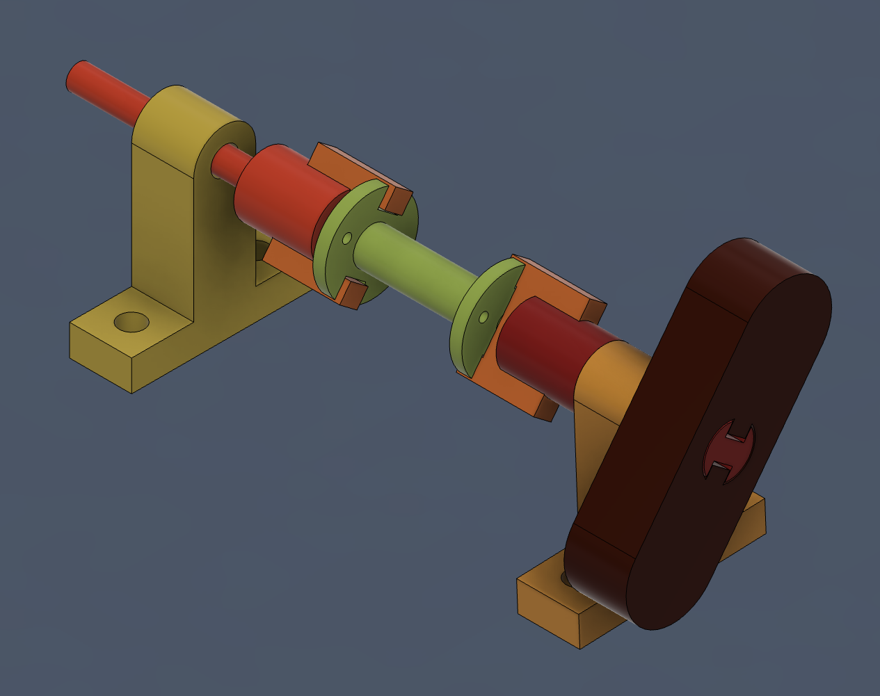
I designed a spool-like part with slots, along with a mechanism to drive it. The challenge was to create parts that would be easy to manufacture using 3D printing. Some of the parts also needed to withstand mechanical loads, which meant considering print orientation as well. To address this, I split the mechanism into several separate components.
The idea was to mount the supports onto a wooden board. I included a spring to make it easy to install and remove the spool. I also made sure to leave clearance in front of the wire exit holes and enough room to secure the incoming wire so that it would not interfere with the winding process.
I printed the parts one by one, testing and adjusting them along the way before moving on to the next piece.
The mechanism is quite small, and when looking at the 3D model it is easy to lose track of the actual dimensions. Once I printed the first parts, I finally got a sense of the scale. I enlarged several components that were too thin. As a result, they looked enormous in the CAD model.
After the first tests, I realized that the spool was not held securely enough on the spring side. This was expected because the shaft is long and slender. I simply added a support to act as a stop.
In the end, the system worked fairly well. The spring rubs against the support and adds rotational springiness, but this is not a significant issue.
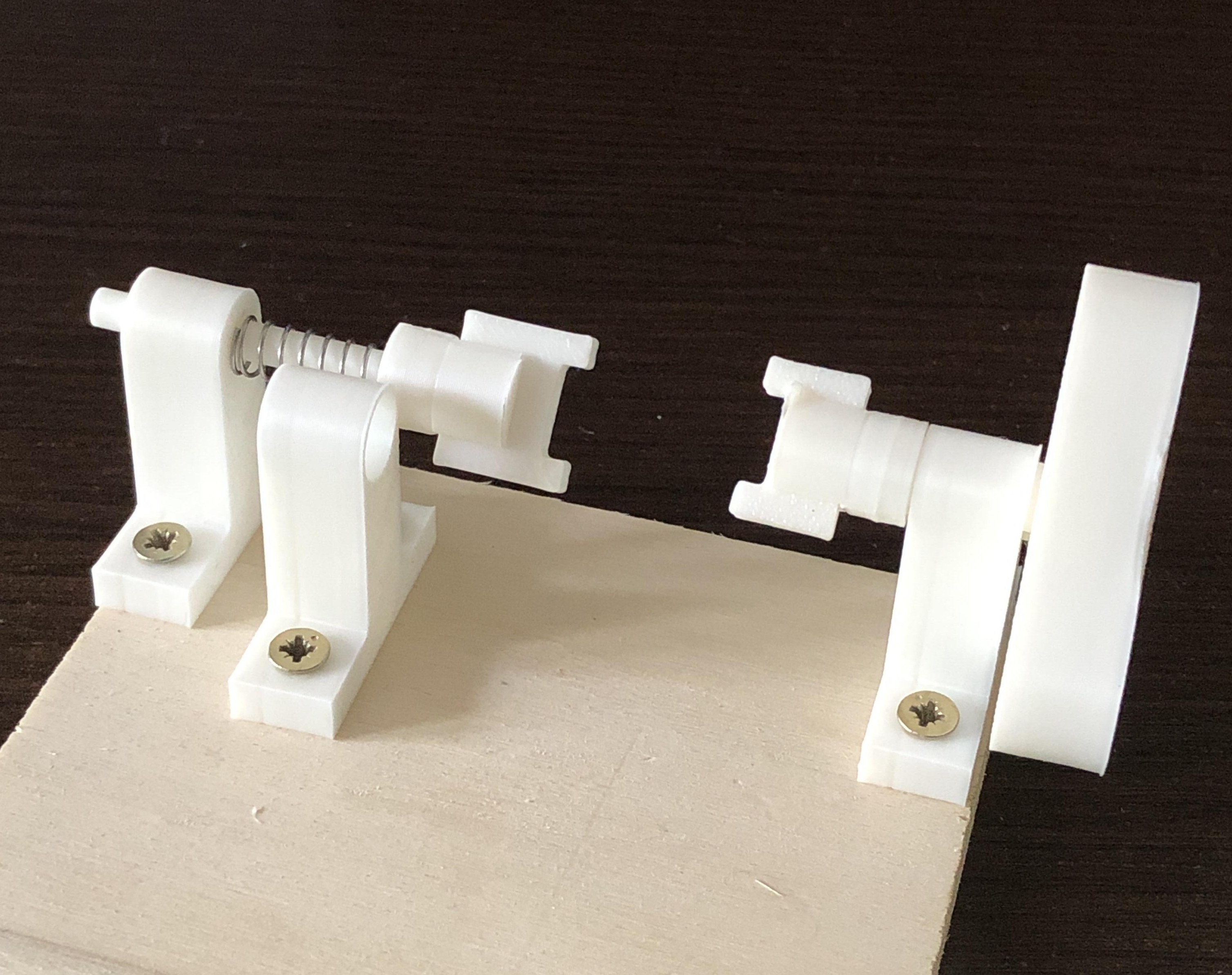
I wound another coil using the same wire. The process went quite smoothly. I measured approximately 40 Ω across the new coil, which seemed encouraging.
However, after another powered test, there was still no detectable magnetic field.
What’s next?
Next I would like to rebuild a coil using fresh wire. Now that I can produce reasonably neat coils, new wire should ensure there are no short circuits within the winding. The winding machine also allows me to increase the number of turns, which is another way to improve coil performance. Using thinner wire could help as well, since it would allow more turns within the same overall volume. Finally, I can try increasing the current by reducing the value of the safety resistor.
To be continued.
I use generative AI to write and/or translate the content featured on this website. AI serves only as a tool for productivity and inspiration, I make sure that the final texts always reflect my personal voice and style.